BLADE ANALYSIS
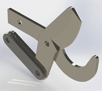

Before beginning analysis, it was necessary to select the design of the Cutting System. Researching what manual and powered tree pruners on the market utilize to cut through tree branches, it was decided to use a Blade and Anvil design. In this system, the Anvil is held stationary by the body of the Pruner. A Blade then rotates, pushing the tree branch downward towards the Anvil. The edge of the blade then shears into and cuts through the tree branch.
With the Cutting System design selected, a tensile tester was utilized to determine the amount of force necessary to cut through a 1 inch tree branch. For this process, a Blade and Anvil from a Fiskars manual tree lopper were used. Knowing this cutting value, work was spent optimizing the geometry of the Fiskars Blade and Anvil to reduce the required force. This included adding the Linkage Pair to connect to the Driving Rod, lengthening the arm of the Blade which attaches to the Linkage Pair (increasing the moment around the pivot point), and altering the neutral axis of the Blade and Anvil (to achieve a 90 degree angle between the Blade and Linkage Pair when maximum cutting force is required).
The image to the right is a reference drawing to quickly visualize the orientation of the Blade to the Linkage Pair at the moment of maximum cutting force. The two solid lines within the circle represent the Blade, the long and horizontal dashed line represents the line of action of the Driving Rod, and the solid line that contacts the circle and the line of action represents the Linkage Pair. This reference drawing also assisted in the design of the Blade Housing, determining how the Blade and Anvil were oriented in relation to the Central Housing Tube.

WELLINGTON & CO.
In collaboration with H.F. Hauff Co. Inc.